

Professional DC Combiner Box Essential Guide for Solar Installations
2026-09-02
Every solar installation hinges on a quiet, often overlooked component—the DC combiner box. Get this wrong, and even the best panels underperform or create serious safety risks. In this guide, we cut through the jargon and break down what installers and system owners actually need to know, drawing on proven insights from Chang Song, a brand trusted for robust combiner solutions. From proper sizing to surge protection and troubleshooting, here's how to make confident decisions without the guesswork.
Nailing the String Count Before You Touch a Single Breaker
There's a moment on every roof where the math either locks in clean or starts whispering doubts. String count isn't a number you trip over mid-install—it's the spine of the whole array, dictating voltage windows, inverter headroom, and how hard those MC4 connectors will work for the next twenty years. Skip the calculation and you're not saving time; you're trading a quiet afternoon for a sweaty rewire under a low sun.
Think of it like tuning a guitar before a show. You can strum all day, but if the strings are off by a half-step, nothing sounds right and the crowd feels it. In PV terms, one string too many pushes your Voc past the inverter's max on a cold morning, while one too few leaves the MPPT hunting for power that isn't there. The sweet spot lives in the temperature-corrected datasheet numbers, not the marketing brochure or a neighbor's guess.
Field veterans check string count before the ladder even touches the gutter. They know module VOC at record low temps, inverter max input, and the exact series fuse rating of every panel in the stack. That pre-work doesn't just prevent a blown fuse or a tripped arc-fault—it keeps the permitting office from flagging your line diagram and the homeowner from wondering why their winter production is limping. Nail this step, and the breaker panel becomes a formality, not a gamble.
Fuse Selection That Survives Real-World Fault Currents
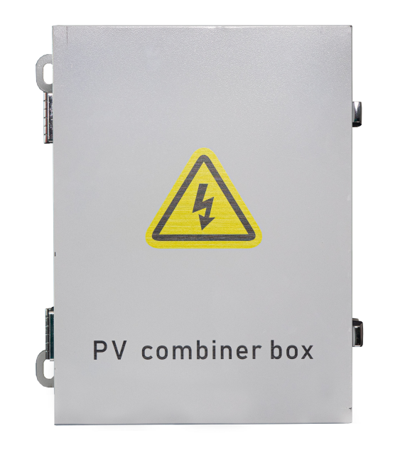
Selecting a fuse that can handle real-world fault currents starts with understanding that laboratory ratings rarely match field conditions. A fuse spec sheet might show a clean interrupting rating, but actual short circuits involve waveform distortion, DC offset, and varying X/R ratios. These factors can push current through the fuse in ways that simple catalog numbers don't capture. Choosing solely based on nominal voltage and ampere rating often leads to premature clearing or, worse, a fuse that ruptures under stress it was never tested for.
Field experience reveals that fault current magnitude is only half the story. The speed at which the fuse must operate—coordinating with upstream breakers or protecting sensitive downstream components—changes depending on whether the fault is bolted, arcing, or current-limited. A fuse that survives a 10 kA test in a controlled lab may fail on a 6 kA fault in a facility with high motor load contribution because the time-current curve shifts. The key is to look beyond published let-through charts and consider the actual system impedance and available fault energy at the fuse's location.
Practical selection means testing against worst-case scenarios that include fuse aging, ambient temperature variations, and manufacturing tolerances. No two fuses from the same batch behave identically under extreme fault conditions. A margin of 15–20% above calculated available fault current is often necessary, not as a safety factor but as a recognition that real faults are messy. The goal is a fuse that not only interrupts the current but does so without damaging its holder, adjacent equipment, or creating a hazard from molten metal ejection.
Enclosure Choices for Coastal, Desert, and High-Humidity Sites
Coastal installations demand enclosures that can shrug off salt spray and constant moisture. Powder-coated stainless steel or marine-grade aluminum tends to outperform standard carbon steel, and gasketed seams prevent chloride-laden air from creeping inside. Look for pressure compensation valves rather than fully sealed boxes—they keep humidity from getting trapped while still blocking saltwater ingress.
Desert sites flip the challenge toward extreme temperature swings, UV exposure, and fine dust. Polycarbonate or fiberglass enclosures with UV stabilizers hold up better than untreated plastics, and light-colored finishes reduce solar heat gain. Filtered vents with replaceable dust screens help keep abrasive sand out of sensitive components without baking them in stagnant heat.
In high-humidity locations, condensation is the real enemy. Enclosures with internal heaters or desiccant packs can prevent dew from forming on circuit boards, while drainage channels and breathable membranes allow moisture to escape. Avoid ferrous metals unless they carry a proven anti-corrosion treatment—stainless or coated alloys are worth the extra cost when the air rarely dries out.
Busbar Layouts That Keep Heat From Shortening Component Life
Thermal buildup in busbar systems rarely comes from a single overload event. It accumulates through tight phase spacing, restricted airflow, and a handful of hot spots that slowly degrade insulation and hardware. Once contact resistance starts climbing, the extra heat feeds back into the same joints, accelerating the wear.
One layout that helps avoid this is spacing phases farther apart than code minimums, especially in long vertical runs. Allowing open air between conductors encourages natural convection. Where possible, orient flat bars on edge rather than stacked face-to-face. That small change increases exposed surface area and lets heat rise without being trapped between layers.
For higher current densities, interleaving busbars or using rounded-edge profiles lowers skin and proximity losses. Keeping the bars away from magnetic enclosures also reduces induced circulating currents. If the layout must remain compact, add passive ventilation slots at the top and bottom of the enclosure rather than relying on active cooling alone.
Field Wiring Techniques Pros Use to Avoid Callbacks
Seasoned electricians know that most callbacks trace back to loose terminations, not faulty devices. They make a habit of forming a clockwise loop on screw terminals so the conductor pulls tight as the screw is torqued. For stranded wire, they twist the strands, then wrap the loop, and sometimes use a fork terminal if the device has a clamp plate. The torque screwdriver gets used on every connection—not just panel lugs—because guessing "tight enough" is how you get heat and flicker a month later.
Another habit that cuts down on repeat visits is leaving the right amount of slack. Pros strip the outer jacket back far enough to fold conductors neatly into the box, but not so much that the wires bind against the device. A gentle S-fold behind the outlet lets you pull the device out later without yanking on the wire nuts. They also label every neutral and hot at the rough-in stage with tape or numbered sleeves. That way, when it's time to trim out, nobody wastes time ringing out circuits or crosses a switch leg.
Finally, wire nuts get a proper pretwist before the cap goes on. Some guys rely on the nut to twist the conductors, but that leaves a weak center and can loosen with vibration. Pros pretwist the stripped ends with linesman pliers, then screw the nut on until the skirt covers all bare copper. A quick tug on each conductor verifies the splice. If you have to add a device down the road, a solid pretwisted joint won't fall apart when you remove the nut.
What a Post-Installation Inspection Should Actually Cover
Most installers assume a post-installation walkthrough means checking whether the unit powers on and calling it a day. That misses the point. The real value is in verifying the details that fail quietly: torque on every accessible fastener, compression of gaskets and seals, and whether drain lines actually slope the right way before they disappear behind a wall.
You also want to test under load, not just at idle. Run the system through a full cycle while watching for vibration, unusual noise, or temperature drift. Check that connections labeled for specific torque values were not over-tightened by feel. If the manual calls for a minimum curing time on adhesives or sealants, document when that window expires and schedule a follow-up before the area gets closed in.
Finally, compare what was installed against the approved drawings and the material list. Missing isolation valves, swapped fasteners, or omitted access panels often show up only when someone actually traces each line. And leave the site with a short defect list—even if everything looks fine, a written record with photos gives the next trade a clear handoff instead of a mystery.
FAQ
It consolidates multiple PV source circuits into a single DC output, giving you a central point for overcurrent protection, surge suppression, and disconnect functions. This keeps the array wiring tidy and makes troubleshooting far less painful.
You'll typically need one when you have more than three strings feeding a single MPPT input, when the inverter lacks integrated string fusing, or when the array is far from the inverter and you want to reduce the number of long home runs. Small residential systems with one or two strings often skip it.
Add up the short-circuit current of all strings landing in the box and multiply by the local safety factor (usually 1.25 in the US, then another 1.25 for fuse sizing). Voltage rating should be at least the array's maximum open-circuit voltage at the coldest expected temperature. Never rely on STC numbers alone.
Look for touch-safe fuse holders, a lockable disconnect, surge protection devices, and a non-metallic or powder-coated enclosure rated for outdoor exposure. Some boxes also include monitoring boards or negative bus bars with separate grounding, handy for larger commercial systems.
Keep it close to the array but accessible from the ground or a service walkway. Avoid placing it directly under drip edges or in full afternoon sun if possible. The enclosure should be vertical, with conduit entries sealed, and there should be enough room to swing the door open and remove fuses without obstruction.
Undersizing the enclosure for heat, using the wrong type of fuse (often confused between gPV and standard DC fuses), landing dissimilar metals without proper treatment, and forgetting to torque connections to spec. Also, people frequently skip the cold-temperature voltage check, which leads to overvoltage trips or damaged components.
At least once a year, but twice is better in dusty or coastal environments. Check torque on every terminal, look for discoloration or hot spots with a thermal camera, verify surge protection status, and clear any debris or insect nests. If the box has monitoring, compare string currents to catch a failing panel early.
Conclusion
A reliable DC combiner installation starts long before the first cable is landed. Count the PV strings per input and verify the combined short-circuit current against the breaker and fuse ratings, leaving headroom for cold-weather irradiance spikes. Fuse selection should be driven by measured or calculated fault current at the combiner, not simply by the module label, because undersized fuses nuisance-trip while oversized ones leave conductors exposed. Enclosure material matters as much as ingress protection: coastal sites need marine-grade aluminum or coated steel with stainless hardware, desert installations call for UV-stable polycarbonate or powder-coated boxes with adequate ventilation, and high-humidity environments demand gasketed, corrosion-resistant designs that prevent condensation pooling.
Inside the box, busbar layout is a thermal problem. Spread high-current conductors apart, use tinned copper busbars with proper torque, and avoid stacking lugs where heat can concentrate. Field wiring should follow a repeatable pattern: label every home run before pulling, maintain bend radius, use ferrules on fine-stranded PV wire, and torque each terminal with a calibrated driver rather than guessing. After the physical work, a post-installation inspection should verify polarity at every input, confirm fuse sizes match the string count, check enclosure grounding and bonding, measure insulation resistance, and thermal-scan under load to catch loose connections before they become callbacks. These habits separate a combiner box that lasts two decades from one that fails in the first summer.
Contact Us
Contact Person: Tonglun Chen
Email: [email protected]
Tel/WhatsApp: 8618906642555
Website: https://www.cncsele.com