

Bubble Sensor Factory: Precision Manufacturing for Reliable Detection Systems
2026-10-14
Bubble sensors rarely make headlines, yet they quietly guard the most critical fluid and gas detection systems. The difference between a missed bubble and a caught one often comes down to manufacturing precision—something Siansonic has obsessed over for years. In this post, we step onto our factory floor to reveal how tight tolerances and uncompromising quality control turn raw components into sensors you can trust when failure isn’t an option.
Cleanroom Beginnings for Every Bubble Detection Core
A bubble detection core doesn't get a second chance at first contact. Every optical window, microfluidic channel, and acoustic coupling layer begins as raw material handled inside a class 100 cleanroom. The gowning routine takes longer than most people expect; one stray skin flake or oil smudge on a lens can scatter enough light to miss a 50-micron air pocket downstream. So we lay out the wafers under laminar flow, check particle counts on the monitor before touching anything, and keep the photoresist bath covered whenever it isn't in use.
There is a quiet rhythm to building these cores in that environment. You learn to move slowly around the spin coater, because a sudden draft can distort the film thickness by a few nanometers—and for acoustic bubble sensors, that is the difference between a clean signal and a blind spot. The alignment marks are etched in the same room where the wet benches sit, so nothing gets exposed to hallway air before it's sealed. Even the epoxy wicking into the capillary gap is dispensed with a foot pedal and a microscope, not by hand. It sounds overcautious until you see a batch fail because someone opened the pass-through door too fast.
Of course, cleanroom beginnings don't end at the air shower. Every tray that leaves the room carries a lot number tied to particle data, humidity logs, and the name of the technician who mixed each solution. When a bubble detection core goes into a dialysis line or an infusion pump, that traceability is the only reason a recall becomes a targeted fix instead of a broad pull. The cleanest sensor starts with the cleanest assumptions: no dust, no shortcuts, and no mystery in the chain of custody.
From Bare Substrate to a Calibrated Sensing Path
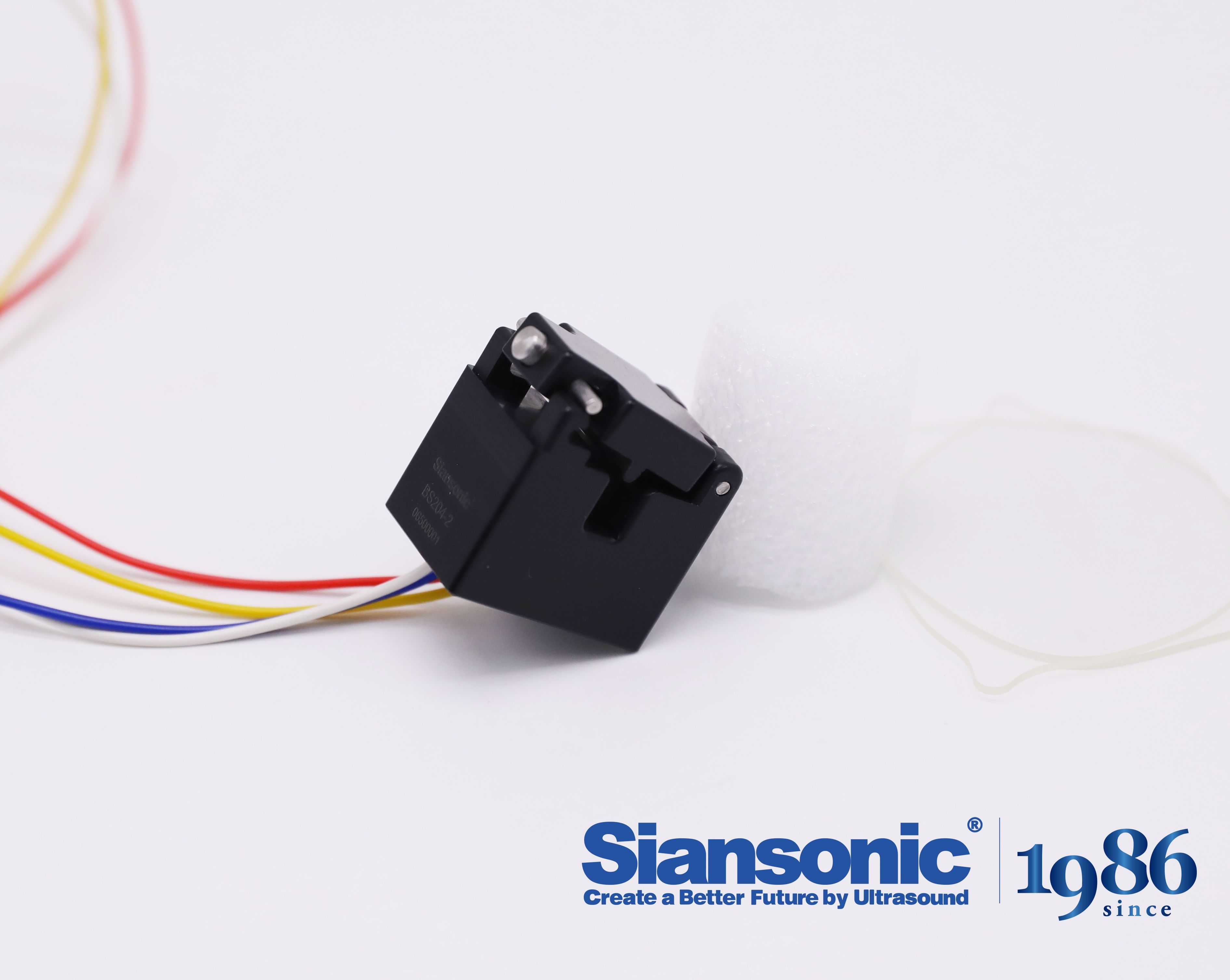
Turning an uncoated wafer into a functional measurement channel rarely follows a straight line. The first step is usually spent cleaning and inspecting the raw surface, because even invisible residues change how the first layer adheres. Once the surface energy is stable, electrodes or waveguides are patterned, and that geometry starts to define where the signal will eventually travel.
Calibration is where most of the hidden work happens. Instead of assuming every device behaves identically, baseline sweeps are run in air, in buffer, or across a known analyte range. Those reference points are then used to trim gain, offset, and drift, so the readout reflects actual changes at the interface rather than batch-to-batch variation.
What emerges is a sensing path with a known personality: its noise floor, sensitivity curve, and useful dynamic range are documented before it ever touches a real sample. That step transforms a bare substrate from a passive platform into a repeatable, trustworthy measurement surface.
Calibration Rituals That Keep False Calls at Zero
Every operator who has chased a phantom signal knows the sting of a false call. It erodes trust, burns clock hours, and sometimes buries a real anomaly under layers of second-guessing. The teams with the cleanest track records treat calibration not as a chore but as a private ceremony—repeating the same sequence of checks, the same reset toggles, the same quiet pause before declaring a reading live. Consistency is the ritual's core: if the baseline drifts, the ritual catches it before the alarm does.
One field-tested approach pairs a daily control sample with an unexpected cross-check. Run a known reference through the sensor at the start of every shift, then again after any environmental shift—humidity spike, power blip, or a door left open. If the reference value moves, the team does not debate the signal; they re-zero and wait for a stable window. The ritual removes ego from the decision. A false call is not a personal failure, it is a break in the sequence, and the sequence can always be repeated.
The final layer is documentation without drama. A small log entry, handwritten or digital, notes the reference value, the ambient conditions, and any deviation. That record becomes the team's memory. When a questionable spike appears, the first question is never "Is this real?" but "Did the ritual hold?" If the answer is yes, the team can act with rare confidence. If the answer is no, they step back, recalibrate, and let the silence prove itself.
Material Choices That Quiet the Noise Before It Starts
Instead of chasing noise after it fills a room, start with what the room is made of. Dense, fibrous materials absorb vibration before it becomes audible. A layer of cork under flooring, felt panels on a shared wall, or heavyweight wool curtains can interrupt footfall and conversation bleed by breaking sound paths at the surface.
Layering different densities does the real work. Soft textiles catch higher frequencies, while rigid but damped composites handle low-end rumble. Recycled denim insulation inside partition walls outperforms standard fiberglass at midrange frequencies and doesn't demand special installation skills. Choose materials that bend rather than ring.
Small swaps often matter more than a full redesign. Replace hollow-core doors with solid wood or acoustically rated versions, add door sweeps, and seal electrical outlets with closed-cell foam gaskets. These choices stop sound from slipping through gaps long before any electronic fix becomes necessary.
Tight Tolerances Without the Rush of Mass Production
Achieving tight tolerances isn't about how many parts you can stamp in an hour. It's about how carefully you can measure, adjust, and hold a dimension when the line isn't pushing you to keep up. In low-volume work, there's room to slow down at the exact moments that matter—checking a bore after a tool change, compensating for thermal drift before it drifts out of spec, or hand-fitting a mating surface that a high-speed process would simply accept as "close enough." That breathing room is what turns a ±0.05 mm print into a ±0.005 mm reality.
Small-batch shops that chase tight tolerances often build their process around verification, not velocity. Instead of relying on statistical process control across thousands of identical parts, they rely on direct inspection of the parts that actually matter. A tenth of a thousandth gets caught because someone had time to put the part on a CMM, not because a histogram told them it might be drifting. This approach doesn't scale to millions of units, but it doesn't have to. It scales to the dozen or hundred parts where a missed tolerance would stop an entire assembly.
The real advantage isn't just the absence of rush—it's the presence of judgment. When you're not locked into a fixed cycle time, you can choose to take an extra spring pass, let a part stabilize to room temperature, or remeasure a critical feature after clamping forces shift. Those decisions don't fit neatly into a production router, but they're exactly what tight-tolerance work demands. Mass production can hold tight tolerances when everything is dialed in, but small-batch work can hold them when everything is not.
Fluid Bench Tests That Approve Every Sensor Exit
Fluid bench testing isn't a formality—it's the gatekeeper that signs off on every sensor exit individually. Unlike spot checks that sample a few outputs and assume the rest behave, this process forces each channel to prove itself under controlled fluid conditions. A sensor might pass overall flow measurements but still have one exit that drifts under backpressure. That's exactly what the bench is designed to catch.
During a typical run, the test rig cycles through pressure ramps, rapid flow reversals, and temperature swings that mimic real-world abuse. Each sensor exit is wired to a data acquisition system that logs its response in real time. If an exit shows even a slight lag, offset, or non-linearity compared to the reference transducer, it's flagged for recalibration or rejection. No averaging across exits is allowed—each channel stands or falls on its own signal.
The payoff shows up later in the field. By approving every exit on the bench, you eliminate the risk of a hidden weak channel that could trigger false alarms, misread fluid levels, or send a controller into limp mode. It's a slower, more tedious approval process, but it's the only way to guarantee that a sensor with a dozen exits behaves like twelve reliable sensors, not eleven good ones and one silent failure.
FAQ
We build every sensor around a closed-loop calibration process that verifies detection thresholds on actual fluid lines, not just bench simulations. Optical components are aligned within micron tolerances, and each batch goes through accelerated life testing with repeated air-in-water cycles.
Instead of relying on manual assembly, we use automated die bonding and laser-welded housings. Inline vision systems inspect lens geometry and electrode placement at three stages, rejecting any unit that drifts more than 0.02 mm from nominal.
Yes, our signal processing firmware analyzes both amplitude and duration of the interruption pattern. Micro-bubbles produce short, sharp dips, while foam creates a longer, noisier disturbance. This lets the sensor ignore harmless foam in many liquid-handling systems.
We offer custom sensor apertures from 1.5 mm to 12 mm and can tune the optical wavelength for fluids that are opaque or strongly colored. Housing materials include medical-grade polycarbonate, PEEK, and stainless steel for aggressive chemicals.
Our production lines are certified to ISO 13485 for medical devices and ISO 9001 for industrial components. We also maintain cleanroom assembly for fluid-contact parts and provide full lot traceability down to raw material batches.
Each sensor carries a factory-set calibration stored in non-volatile memory. We also perform temperature cycling from -20°C to 70°C before packaging, which catches drift that would only appear after environmental stress.
Standard sensors respond within 5 milliseconds, which is fast enough for infusion rates up to 2,000 ml/h. For high-flow production lines, we offer a high-speed variant that triggers within 1 millisecond without increasing false positives.
Yes, we supply reference circuits, sample code for common microcontrollers, and analog or digital output options. Our engineers can also review your PCB layout and fluid path design at no extra cost during the prototyping phase.
Conclusion
Inside the bubble sensor factory, every detection core starts in a cleanroom where airborne particles are kept away from bare substrates. From that point, each substrate moves through precise deposition and patterning steps to become a continuous, calibrated sensing path—one that carries signal without distortion. Material choices happen before assembly, using specialty alloys and insulating layers to suppress electrical and thermal noise at its source. Tolerances stay at micron level, but the production rhythm is measured, never rushed, so batch pressure cannot alter the geometry of a single sensing element.
Calibration is handled like a ritual, not a checkbox. Each sensor is exercised across its full operating range, and trip thresholds are tuned so tightly that false positives remain at zero while real bubble events still trigger without delay. No unit leaves the floor until it passes a fluid bench test that replicates actual flow conditions—varying viscosity, pressure, and bubble size—and shows repeatable response within a narrow band. That sequence of clean fabrication, quiet materials, careful calibration, and final hydraulic approval is what keeps these detection systems reliable in the field, where a missed bubble or a phantom alarm can carry real consequences.
Contact Us
Contact Person: Ivy Zhang
Email: [email protected]
Tel/WhatsApp: +86 1081502288
Website: https://www.siansonic.com/